Design Summary
The wastewater will enter the treatment site at the north end. The flow will be split into two Oswald ponds, where an aerobic and anaerobic process will treat the water. These Oswald ponds are sized so that one can be taken out of service for maintenance or repairs, without impairing the function of the other. From the Oswald ponds, the wastewater will flow by gravity into a series of channels which will dispose of the water through percolation, evaporation, and transpiration. The system is considered a total retention system because it does not discharge into a nearby body of water. For this reason, there will be no disinfection incorporated into the design. The system is designed to treat 20 years worth of wastewater.
Data
Excel Spreadsheets:
Design Flow
Oswald System Design Calculation
Preliminary Calculations for Lagoon Alternative
Flow Balance (Treatment system & Disposal Basin)
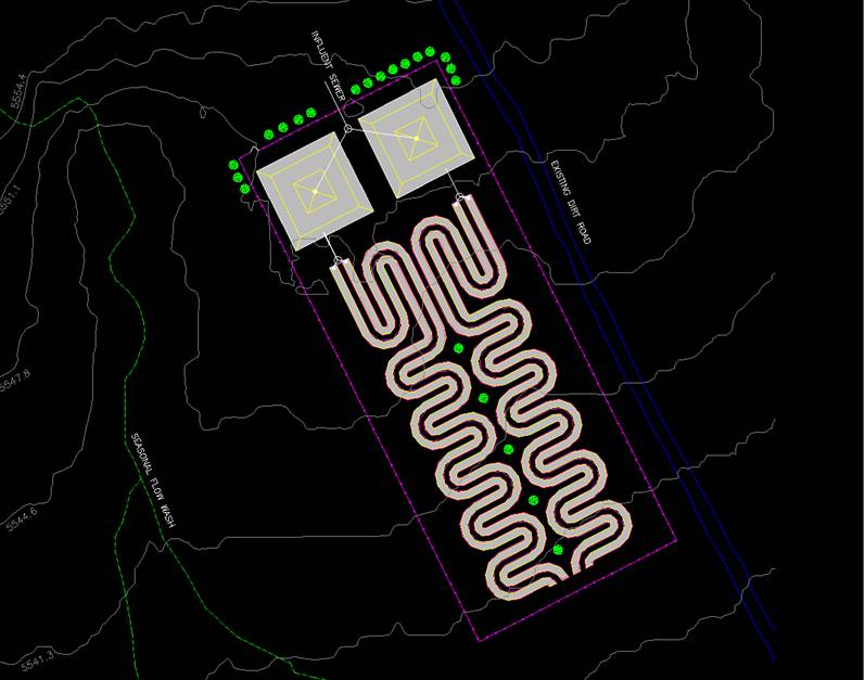
Site Plan CAD Drawing:
The pink line around the 20.5 acre perimeter represents a chain link fence.
The Green circles are
willow trees, which serve as a wind barrier. There are two Oswald systems
drawn in
yellow, hatched with gray. These Oswalds are 253' by 253', covering a
combined area of 2.94 acres. There is a seventeen foot wide dirt road
between each of the channels to provide
accessibility for maintenance and/or repairs. The channels are 23' wide
and sinuous in design. The channels cover approximately four acres.
White lines denote 8" sewer line. Circles on the sewer lines denote
flow splitters.
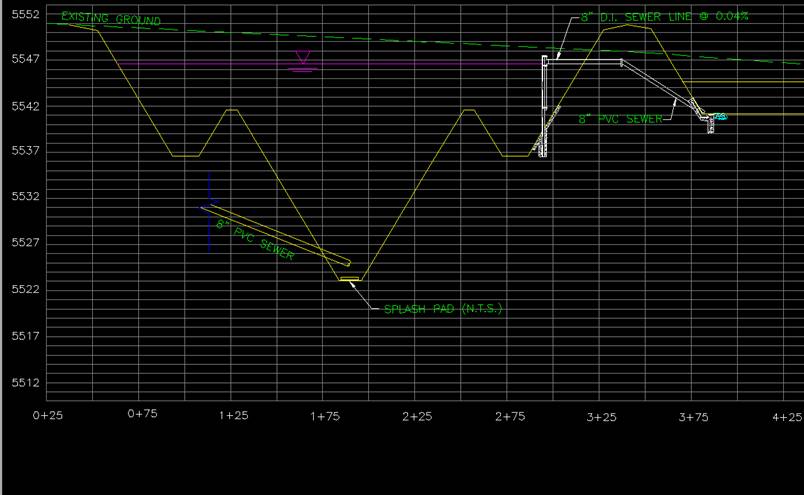
CAD Drawing of Oswald Pond:
The Oswald ponds are 23.5 feet deep, measured from the water surface to the
bottom. The water surface is represented by the pink horizontal line with
the triangle pointing at it. The green dashed line represents the existing
ground before excavation and the yellow line represents the excavated contours
of the Oswald system, in profile. The white structure on the right is the
baffle which transports water from the Oswald to the wetland channels. As
you can see from this drawing, the influent sewer enters the Oswald at the
bottom of the pit.
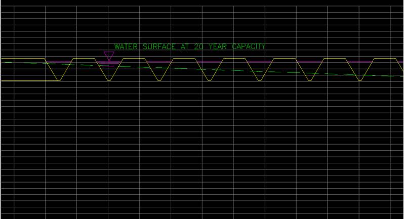
CAD Drawing of Channels:
The channels are shown in profile view below. The depth from the water
surface (pink line) to the bottom of the channels is 3 feet. The channels
were designed at a 3:1 side-slope, and have 6 inches of free-board from the
water surface, at capacity, to the road surface. The roads are 17 feet
wide, and the channels are 23 feet side at their widest point. The green
dashed line shows the existing ground before excavation, and the yellow lines
show the channels and roads in profile.
![]()
![]()
![]()