Project Documents
Reports and Presentations
- Presentation 1: Initial research into project and field
- Presentation 2: Design comparisons and mathmatical modeling
- Presentation 3: Proposal and validation of final design
- Report 1: Details of first half of semester
- Report 2: Progress of first semester work
- Final Report: Full documentaion of project across both semesters
Prototypes
- Prototype 1: Initial test of translational system and Arduino code
- Prototype 2: Initial test of rotational system and Arduino controlled stepper motors
Build and Test Updates
- 33% build: 99% CAD, 95% BoM, 55% Manufacuring
- 67% build: 100% CAD, 100% BoM, 80% Manufacuring
- 100% build: 100% CAD, 100% BoM, 100% Manufacuring
- Full CAD: Drawing of all parts used in assembly
- Project Testing: Experiments to test the completeness of the project with respect to the Engineering Requirements
Undergraduate Symposium Reports
- Ugrad Poster: Poster description of project presented at the Undergraduate Symposium
- Ugrad Presentation:Presentation given at the Undergraduate Symposium
Project Gallery
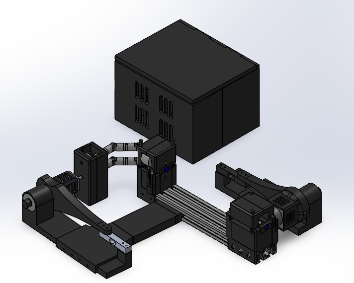
Full System Design
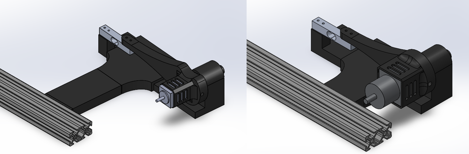
Translation System Assembly
This design was made according to research and modeling found in the above documents. The system is designed to slide on the framing rail for securement and positional adjustment. The bottom component contains the motor attached to a driving roller and a plain bearing on a steel shaft. The catheter is fed through the small hole seen in the center right of the image. The motor is given a small step size to provide incremental pushes to the catheter and the urethane rollers provide enough friction to guide any catheter. The top section rests on the bottom held in place by two shafts and is moved two micro lead screws. This section contains two more urethane rollers aligned with those on the bottom and is weighted to add more friction to the system.
Rotation System Assembly
The rotation model was made in a similar way to the translation system. However, to induce rotation, the catheter is fed axially to the driver wheels. This allows for a twisting motion to be applied onto the catheter over the pushing force caused by the translation system. In this system, both the top and bottom rollers are driven through the use of a gearbox attached to the motor. The gearbox also helps to move the motor out of the path of the catheter giving it clear movement.
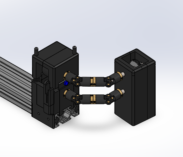
Sensor System Assembly
This sensor system allows the movement of the motor to be recorded. In both of the above systems, the motor is locked in place with a lever arm set up. The motor is placed in a cage that restricts all degrees of freedom except for rotation using bearings. As the motor turns the driver roller, the reactionary forces of this rotation are passed through the lever arm and apply strain onto a whetstone bridge with strain gauges attached. the gauges record the movement and outputs a voltage signal to an H-bridge and Arduino system that turn the voltage into a digital signal and record its data
Fall 2024 Gantt Chart
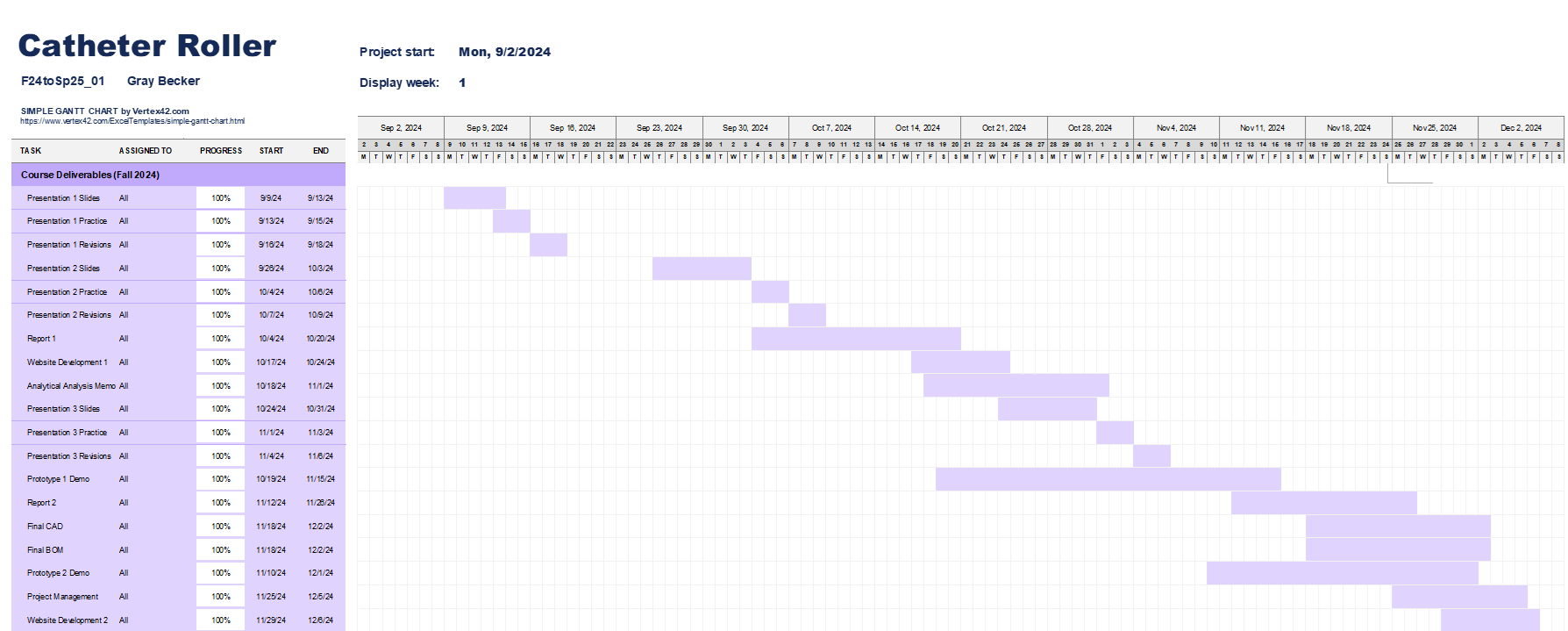
Schedule for the fall semester wih all major assignments and the time frame established to complete them
Spring 2025 Gantt Chart
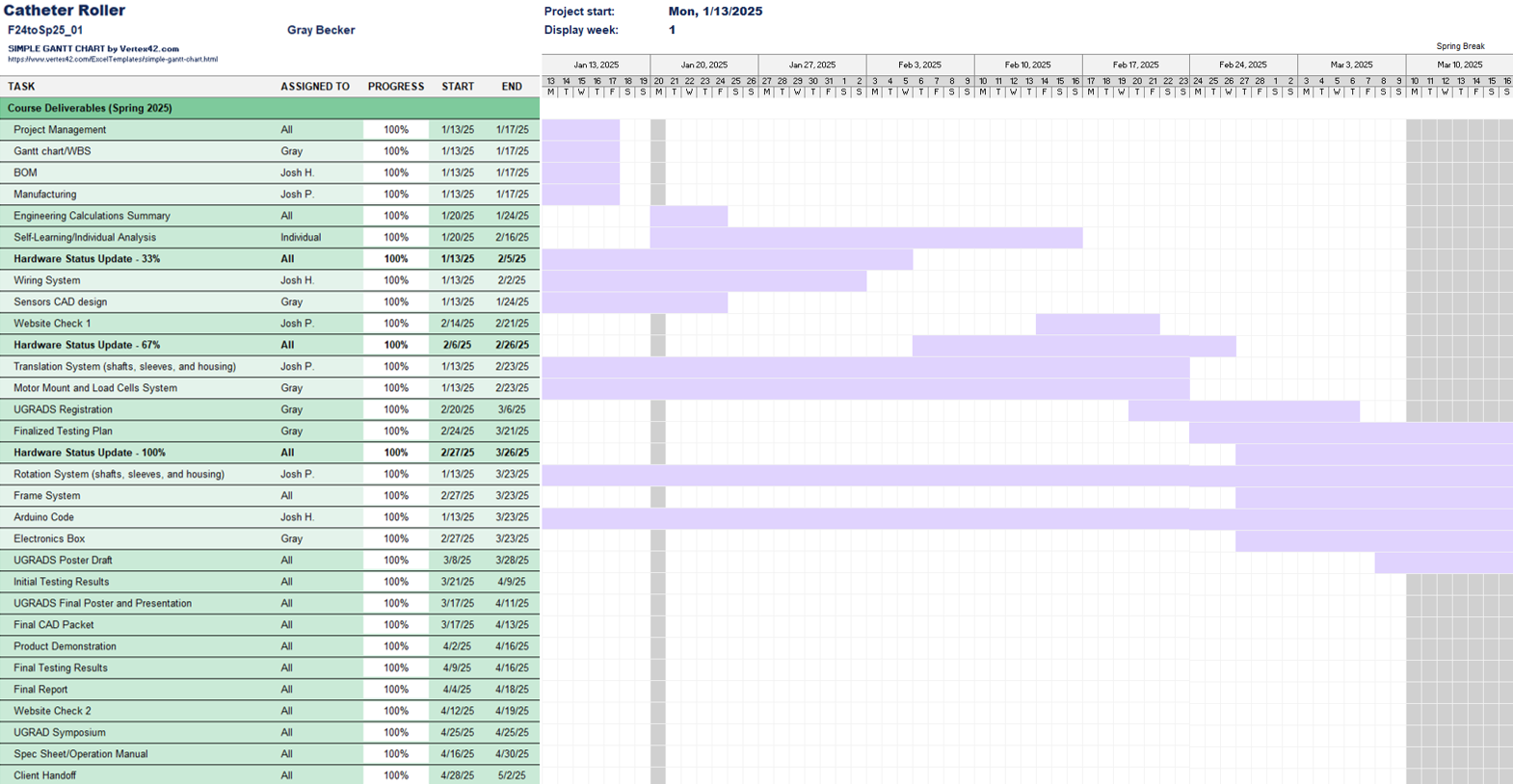
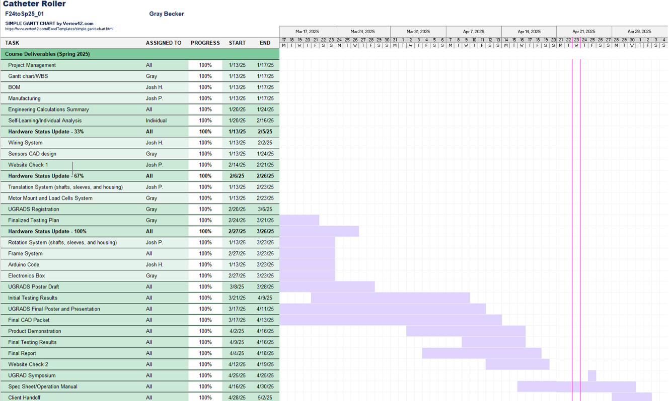
Schedule for the spring semester with all major assignments and the time frame established to complete them
Budget Summary
.png)
Full spending for project