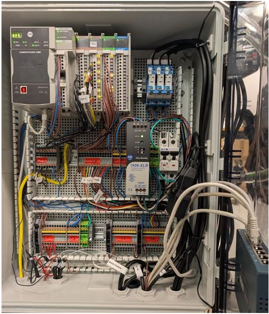
Fig. Main electrical box
Automation dry run
Adsorption stage
Air evacuation stage
Vapor stripping stage
Final desorption stage
Pressurization stage
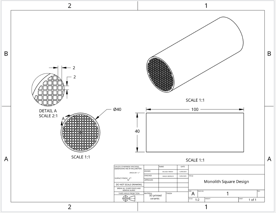
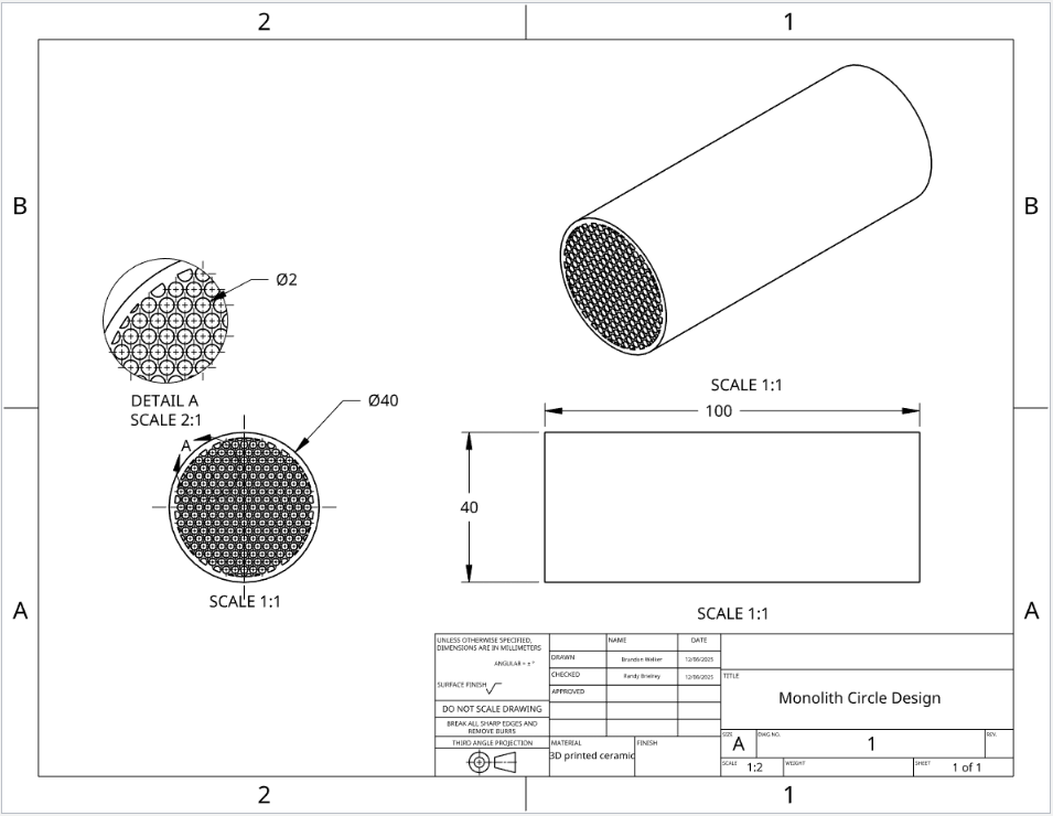
3D peinting monolith sorbent structure
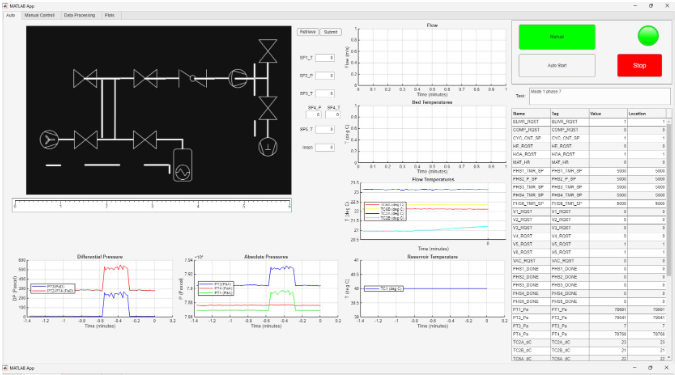
Fig. User interface main control panel
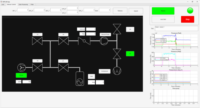
Fig. User interface manual control panel
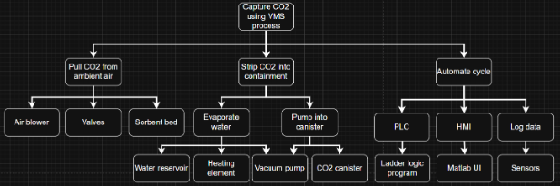
Fig. Functional decomposition of entire system
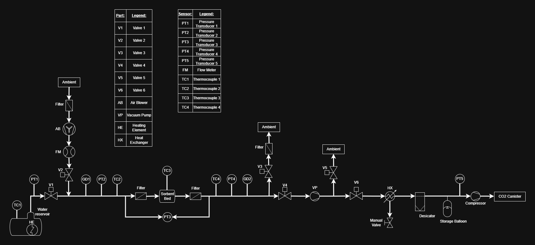
Fig. PID diagram
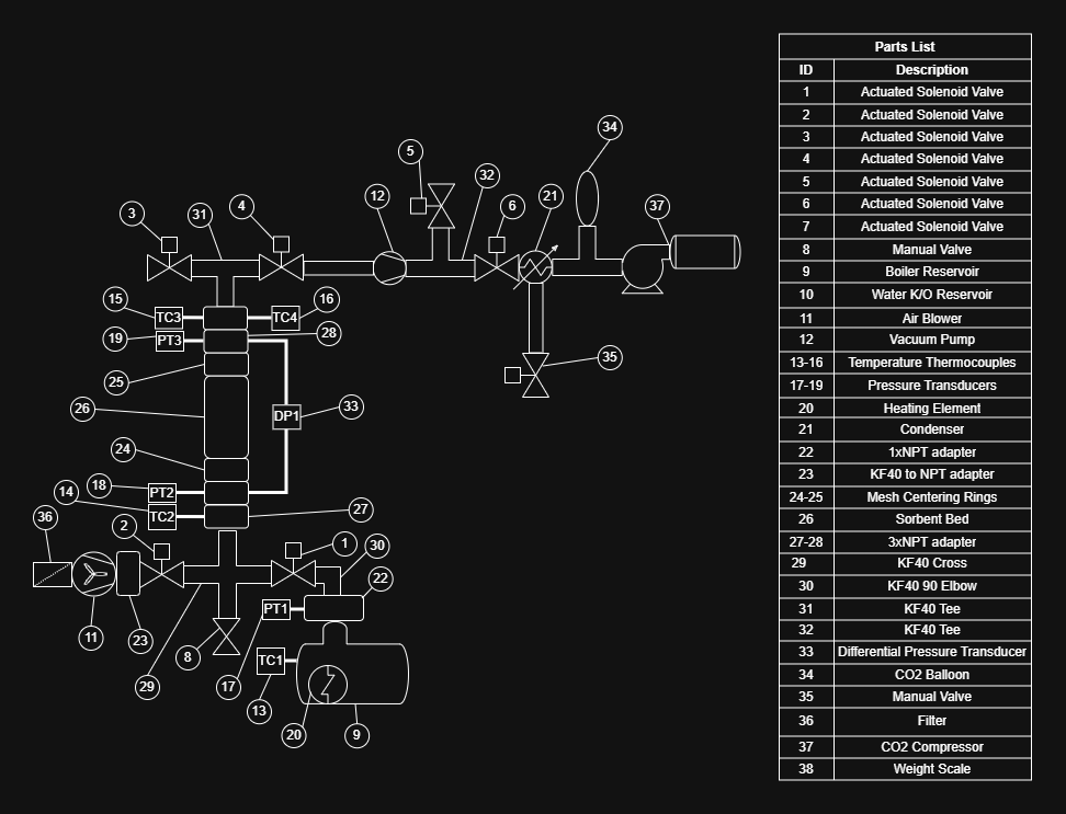
Fig. Physical diagram
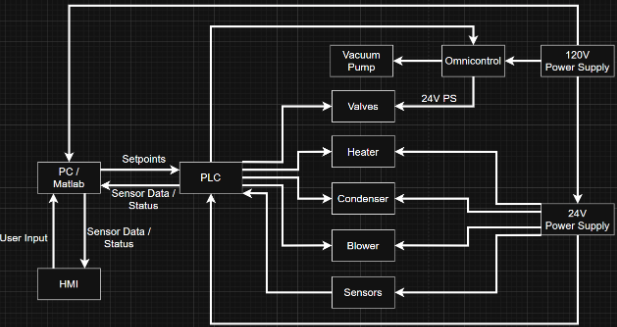
Fig. Control Block Diagram
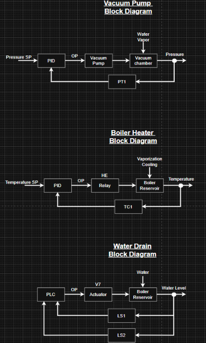
Fig. Subsystem block diagram
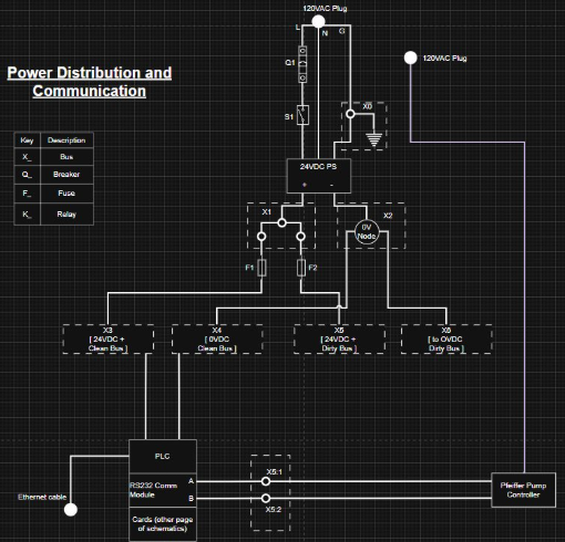
Fig. Power and control diagram

For our initial prototyping ANSYS fluent was used to model the behavior of water vapor as it passes through various sorbent structures. Various graphs and visuals from the data can be seen below. More information is available in report 2.
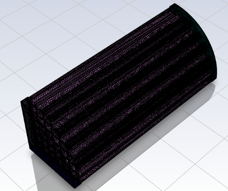
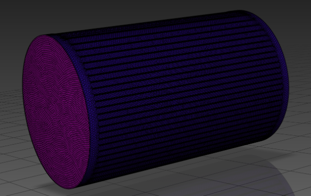
Fig. Quarter of monolith mesh and full laminate mesh
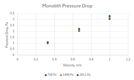
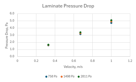
Fig. Pressure drop for monolith and laminate structures at various saturation pressures and velocities
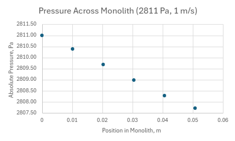
Fig. pressure drop across length of monolith
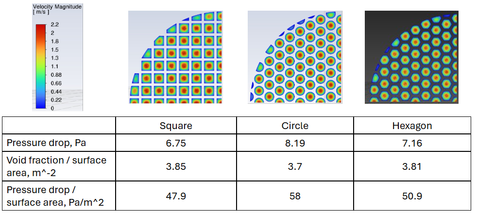
Fig. Comparison of channel geometry for monolith structure
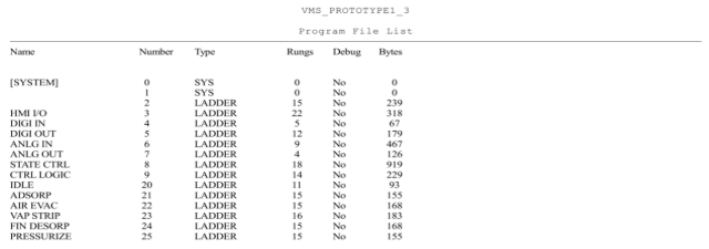
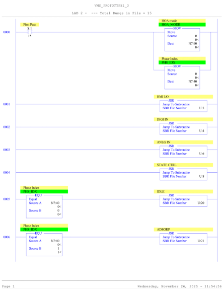
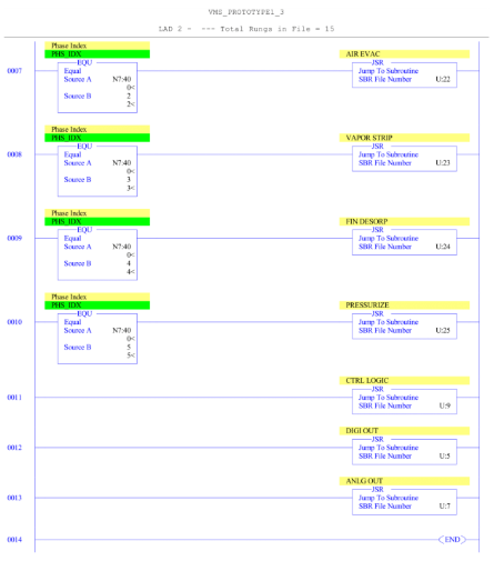
For our initial prototyping, we began to develop a PLC control loop to control the final apparatus. A summary of ladders and the first ladder may be seen below. More information is available in report 2.