Abstract
Our team aims to design a renewable heating system that utilizes renewable energy sources, mainly solar
energy. The purpose of this project is to supply sufficient heating to the Renewable Energy (RE) building
during the cold winter months, utilizing solar energy to protect the building’s battery storage and as an
alternative to non-renewable energy sources such as fossil fuels.
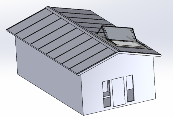
To achieve this, our team refurbished two recycled solar air collectors and mounted them on the eastern side
of the building's roof. The solar panels have two primary energy inputs: the existing photovoltaic solar panels
and electric batteries. The system is connected through custom-built ductwork and a control network that
distributes heated air throughout the building. Two vents are located in the building's larger room while one is
located in the smaller room.
From engineering analyses, including modeling, simulations, and hand calculations, results show that the solar
air collectors can provide a sufficient amount of heating during the winter, covering about one half of the
building’s heating demand. From results, the design demonstrates it can account for safety, efficiency, and
performance. Although the building requires supplemental heating in the winter, our project demonstrates the
scalability of solar air heaters and shows that we have met our goal to lower carbon emissions, reduce costs,
and extend the life of existing clean energy.
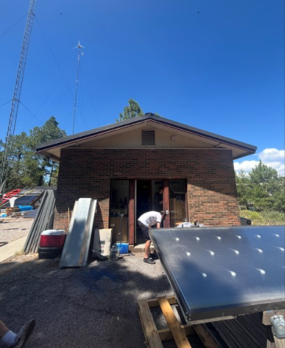
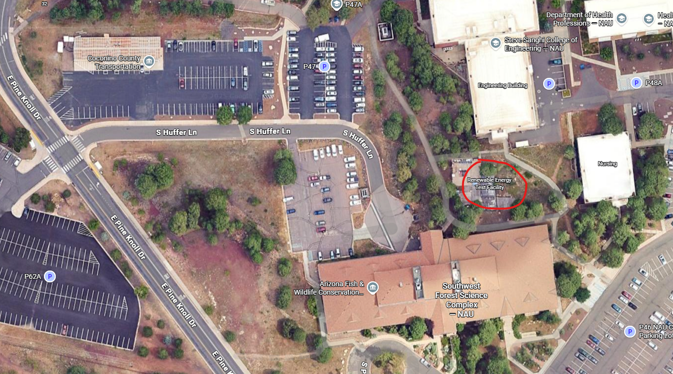
Location & Maps
The project is based at Northern Arizona University’s Renewable Energy Test Facility (RETF). The solar air heater will be installed on the roof of the RETF building and ducted into the thermal battery room.
Project Constraints
- Budget: $1000 capstone funding plus $2000 allocated for roofing work.
- Codes / Standards: Must follow 2021 IMC and relevant ASHRAE recommendations.
- Timeline: August 2024 – December 2025 (design, build, test, final report).
Tasks (Roles)
- Jacob Apodaca: Testing & data collection (airflow, ΔT, thermal performance).
- Brendan Frazier: Project and logistics management, scheduling, communication.
- Tyler Hedgecock: CAD modeling, drawings, and design documentation.
- Joseph Meza: Budgeting, purchasing, and integration analysis.
- Calvin Schenkenberger: Manufacturing lead; fabrication and assembly.
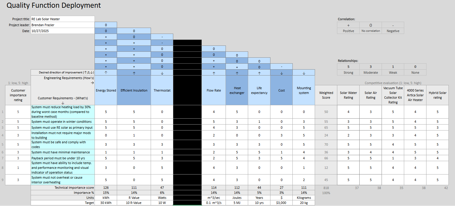
QFD & Decision Matrix
Quality Function Deployment (QFD)
Customer needs are translated into engineering targets to compare air-based and water-based storage concepts. The matrix helped prioritize capacity, cost, safety, and maintainability when down-selecting the final design.
Weighted Decision Matrix (Water vs. Air)
Weighted scores for each concept. Higher total indicates the selected design.
| Criterion | Weight | Design 2 (Water) | Design 5 (Air) |
|---|---|---|---|
| Energy Stored | 25% | 21.2 | 19.0 |
| Insulating Power | 20% | 13.2 | 14.6 |
| Head Pressure | 5% | 2.6 | 3.4 |
| Exchanger Efficiency | 15% | 11.6 | 11.2 |
| Life Expectancy | 20% | 15.4 | 18.2 |
| Cost | 15% | 9.8 | 12.8 |
| Total | 100% | 73.8 | 79.2 |
Final Design Details
The final collector uses perforated aluminum plates inside a polycarbonate enclosure with insulated backing. Ambient air is pulled through the perforations, heated by solar radiation, and routed through roof ducting into the thermal battery room. The system is designed to be modular so that panels and fans can be serviced or upgraded without major rework to the roof or interior. Mounting, duct transitions, and wiring are all sized to support future expansion while staying within current budget and safety constraints.
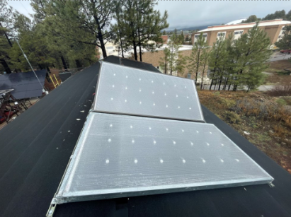
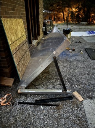
Hardware
The hardware subsystem includes the solar air heater panel, roof rack, and structural framing that carries loads into the existing building. The mounting geometry is designed to match the RETF roof pitch while maintaining the correct panel tilt to capture winter sun. Fasteners and brackets are selected to resist snow, wind, and thermal cycling over the lifetime of the system. Access panels and clearances are built in so that fans, sensors, and seals can be serviced from the roof without disturbing the main structure. Overall, the hardware layout is intended to be robust, simple, and repeatable for future installations.
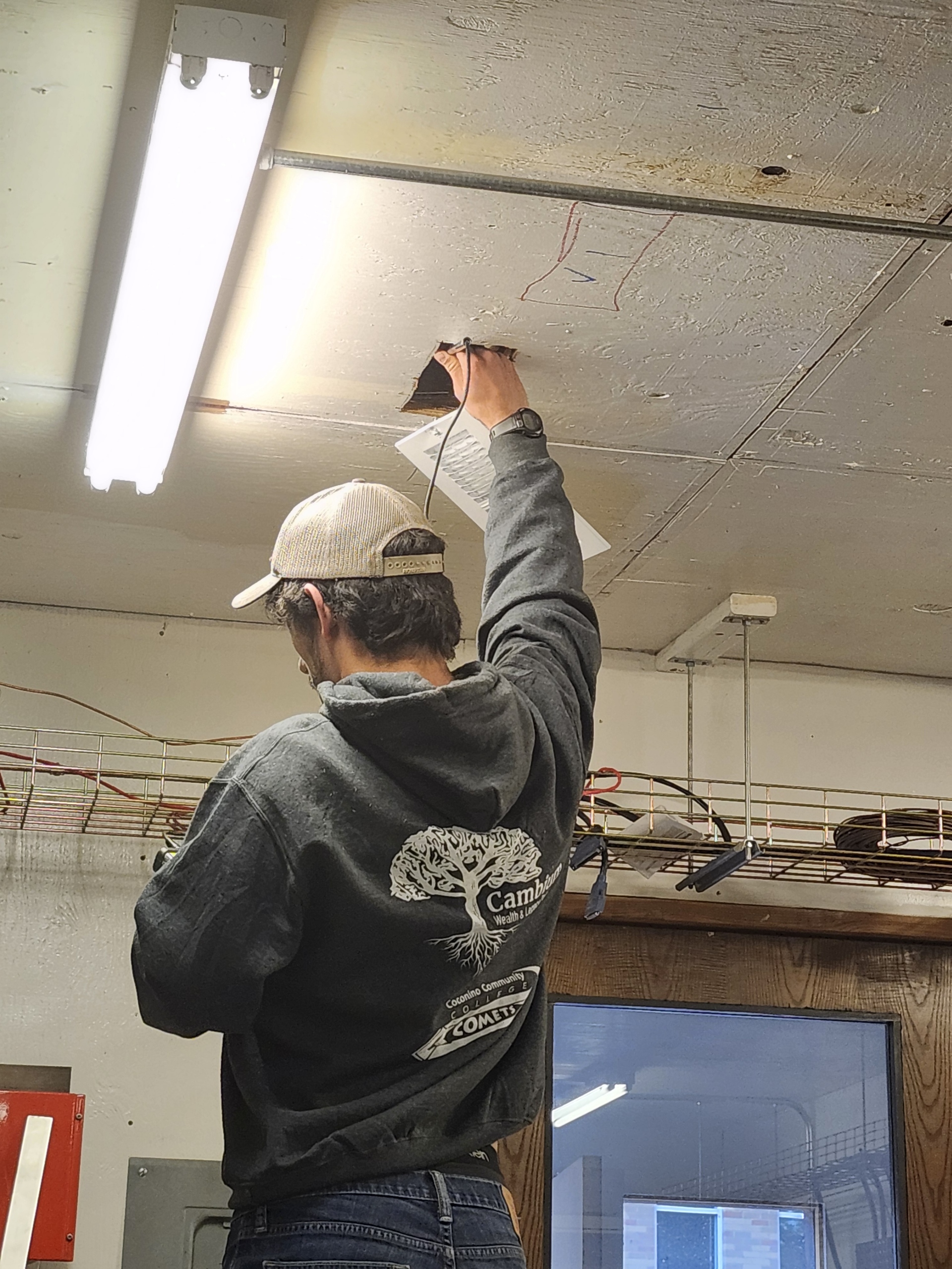
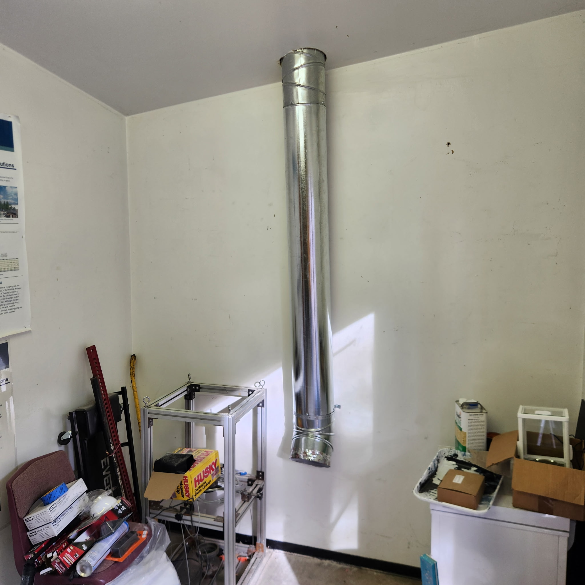
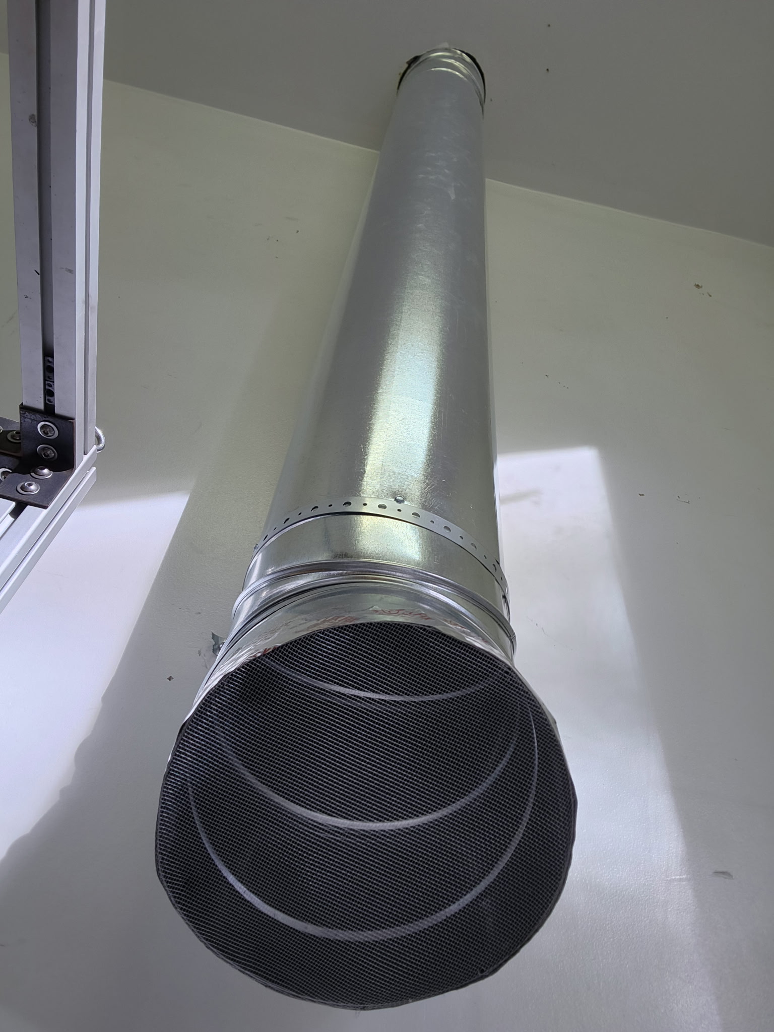
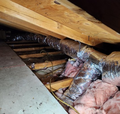
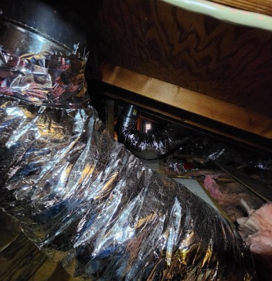
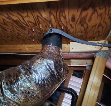
Duct Work
The duct work subsystem carries heated air from the collectors on the roof down into the thermal battery room. Flexible insulated ducting is routed through the attic to minimize pressure losses and avoid existing structural members. Joints and transitions are sealed to reduce leakage and protect against condensation in cold conditions. Support straps and blocking are added where needed so the ducts do not sag or rest on insulation over time. The goal is to deliver as much of the captured heat as possible to the batteries while keeping noise and flow restrictions low.
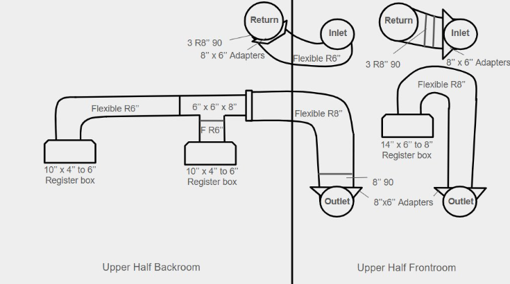
Ductwork Diagram
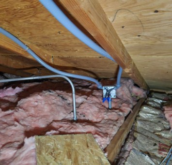
Electrical
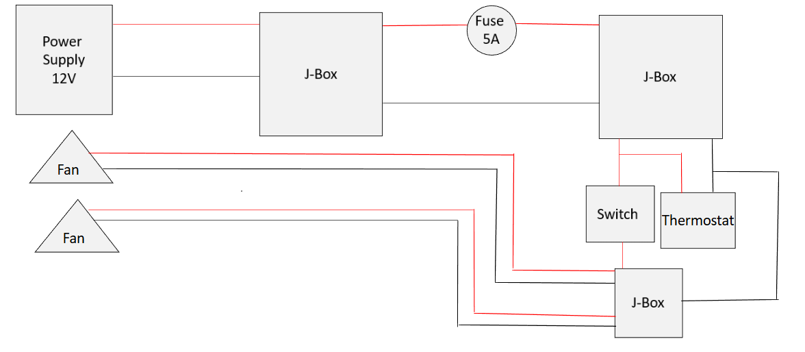
The electrical subsystem powers the fans and controls when the solar air heater operates. A 12 V supply feeds a series of junction boxes, with a 5 A fuse providing overcurrent protection. A thermostat and manual switch are wired into the circuit so the system can turn on automatically based on temperature, while still allowing the operator to override it. All wiring in the attic is run in conduit or stapled neatly to framing to reduce trip hazards and protect the cables from damage. The wiring diagram below summarizes how power, fans, and controls are interconnected.
Electrical Diagram
CAD Drawings
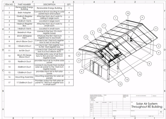
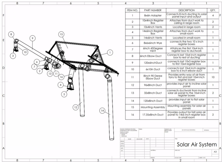
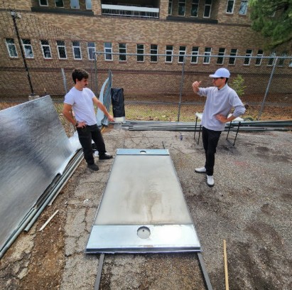
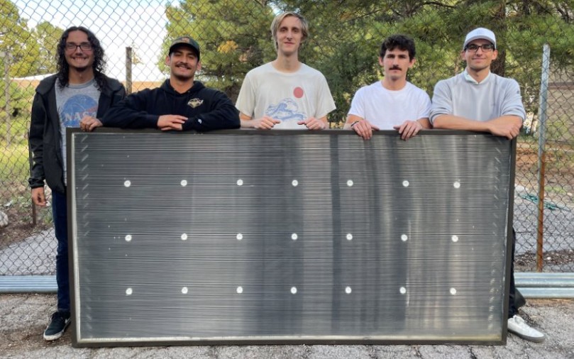
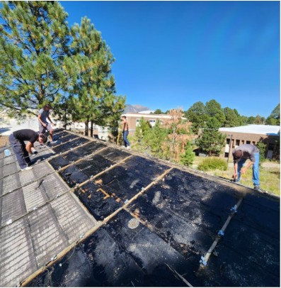
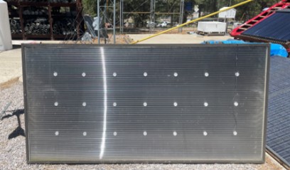
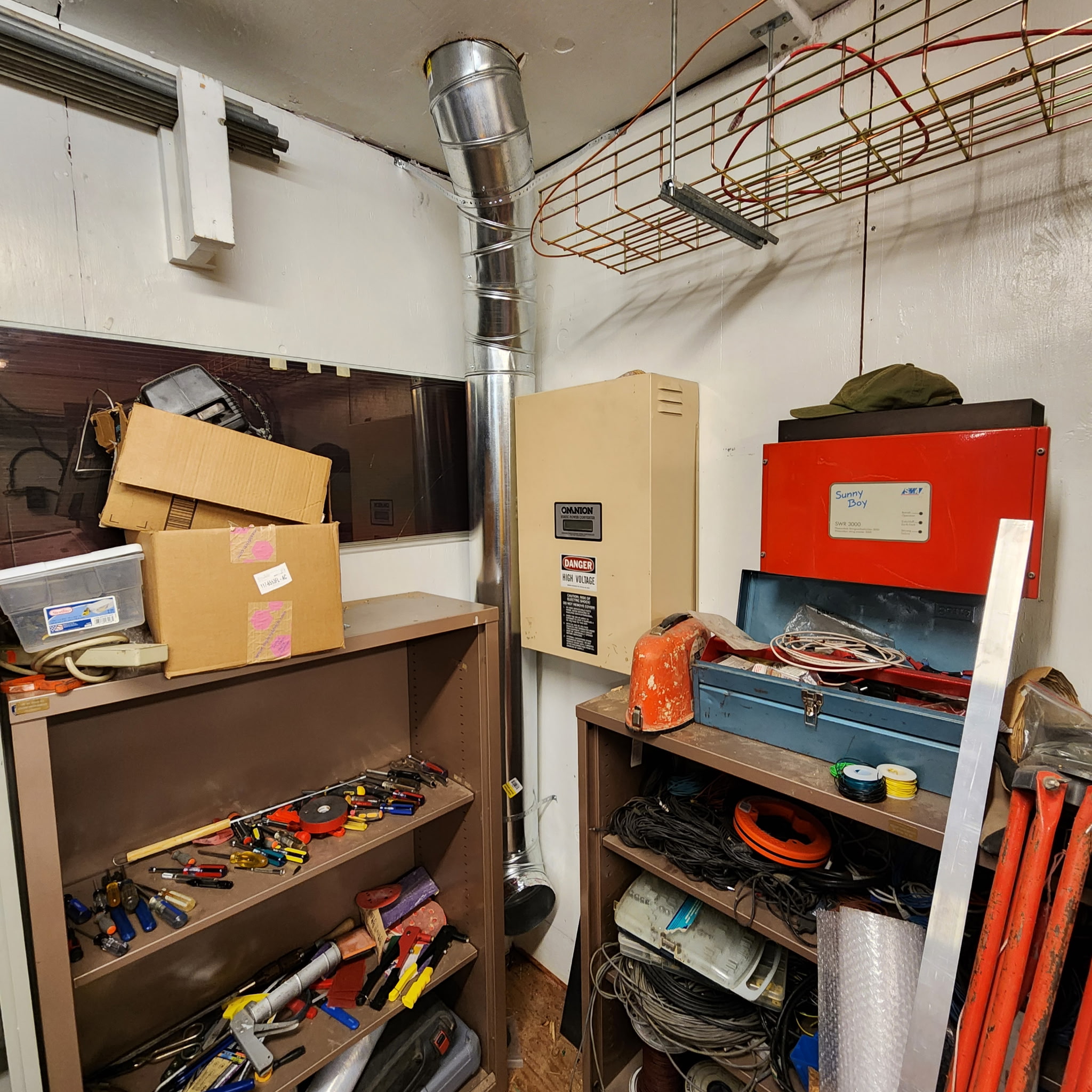
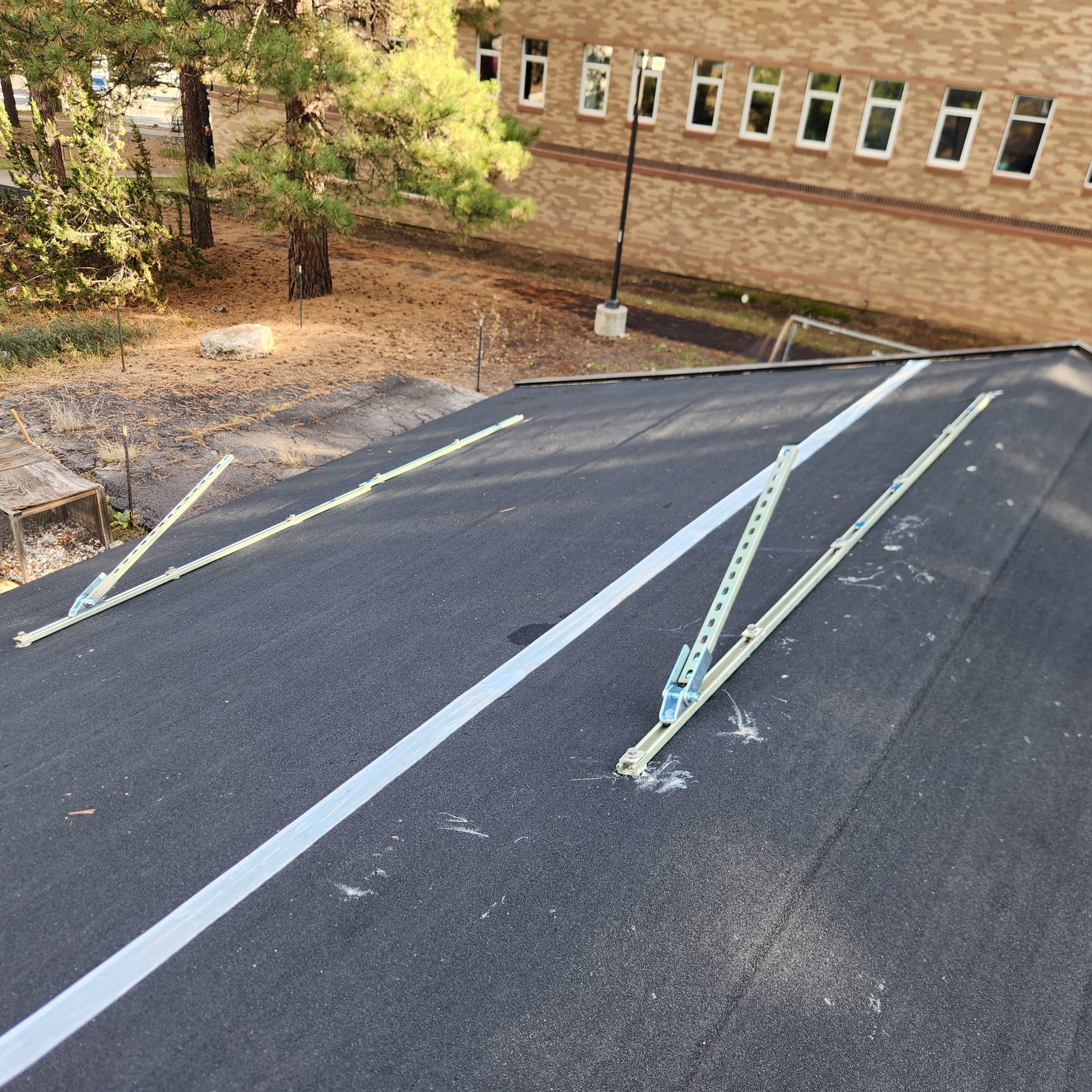
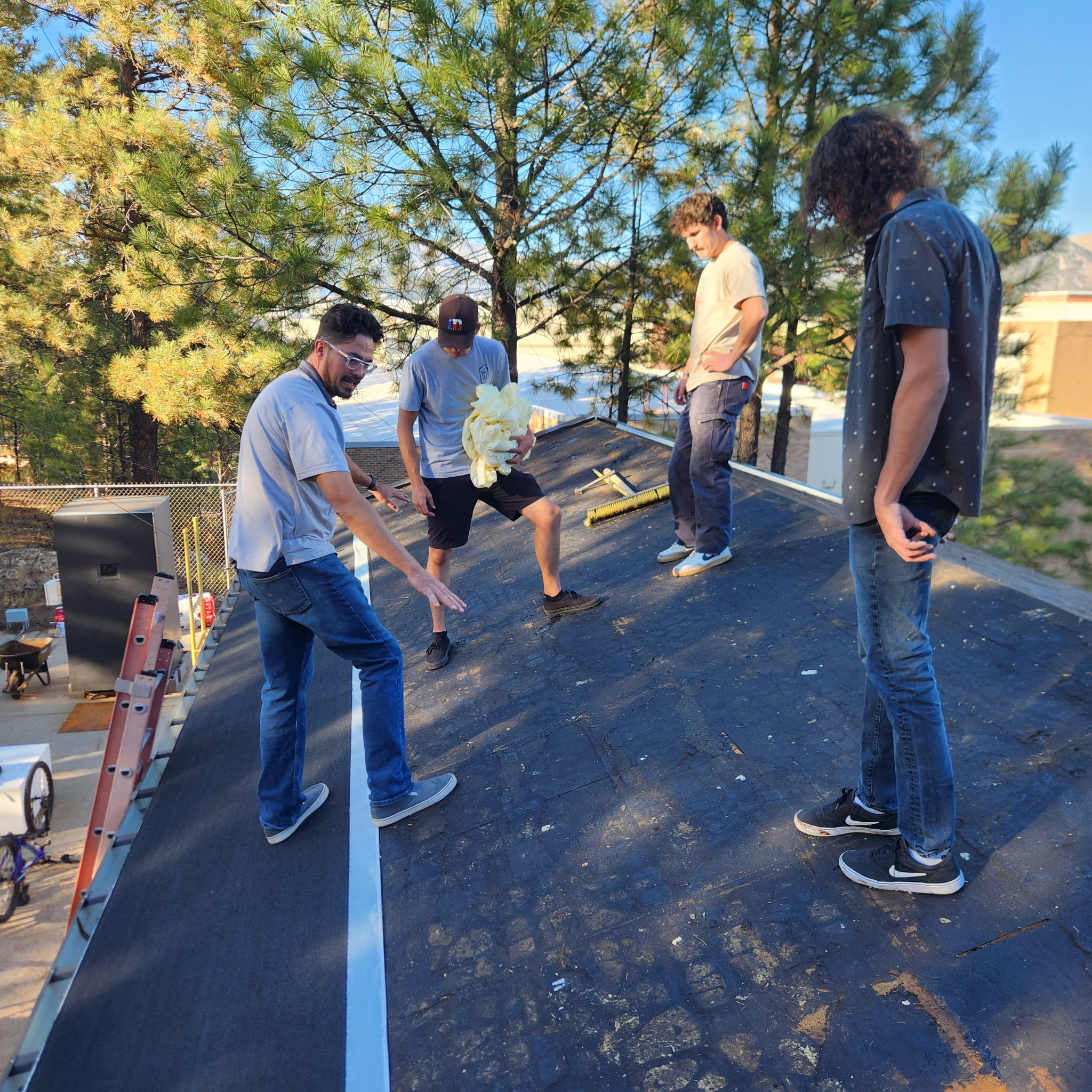
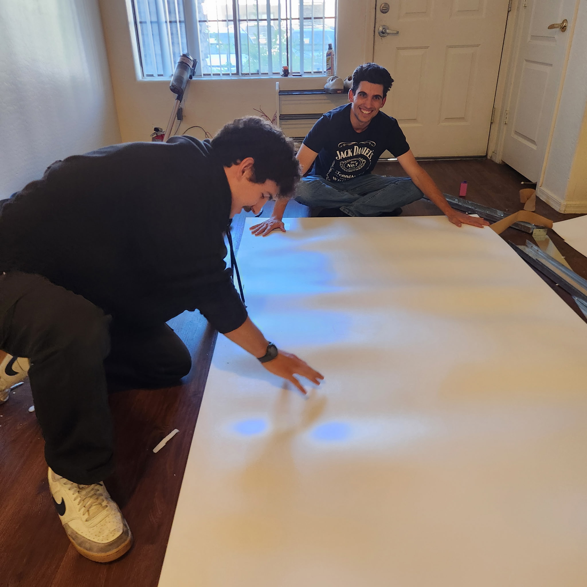
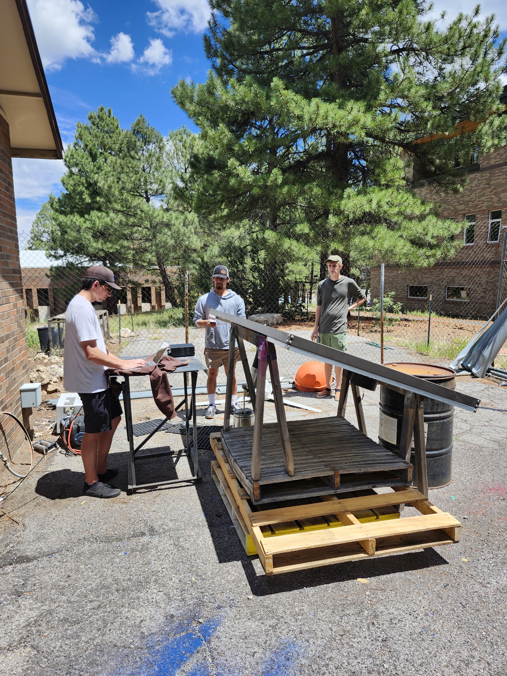
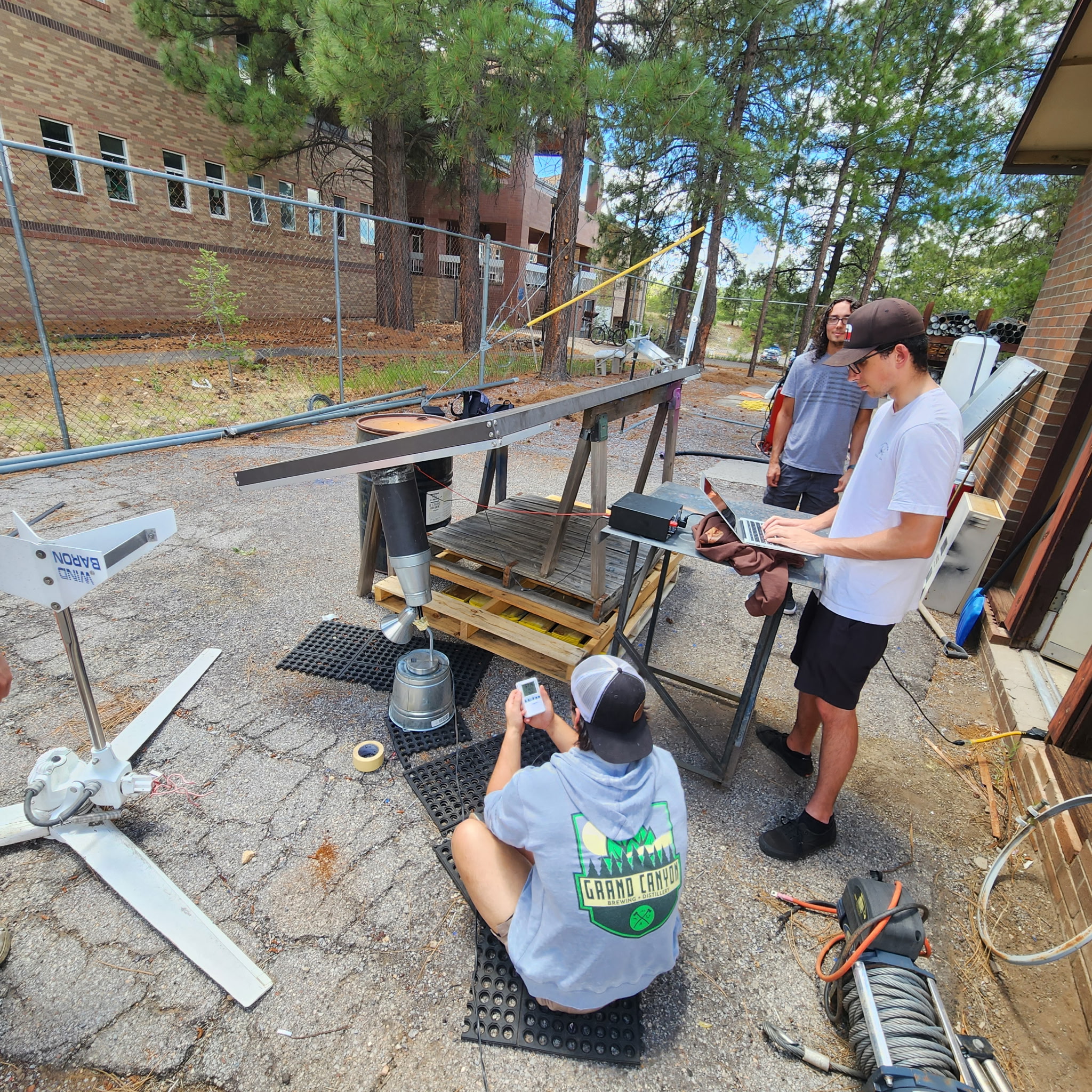
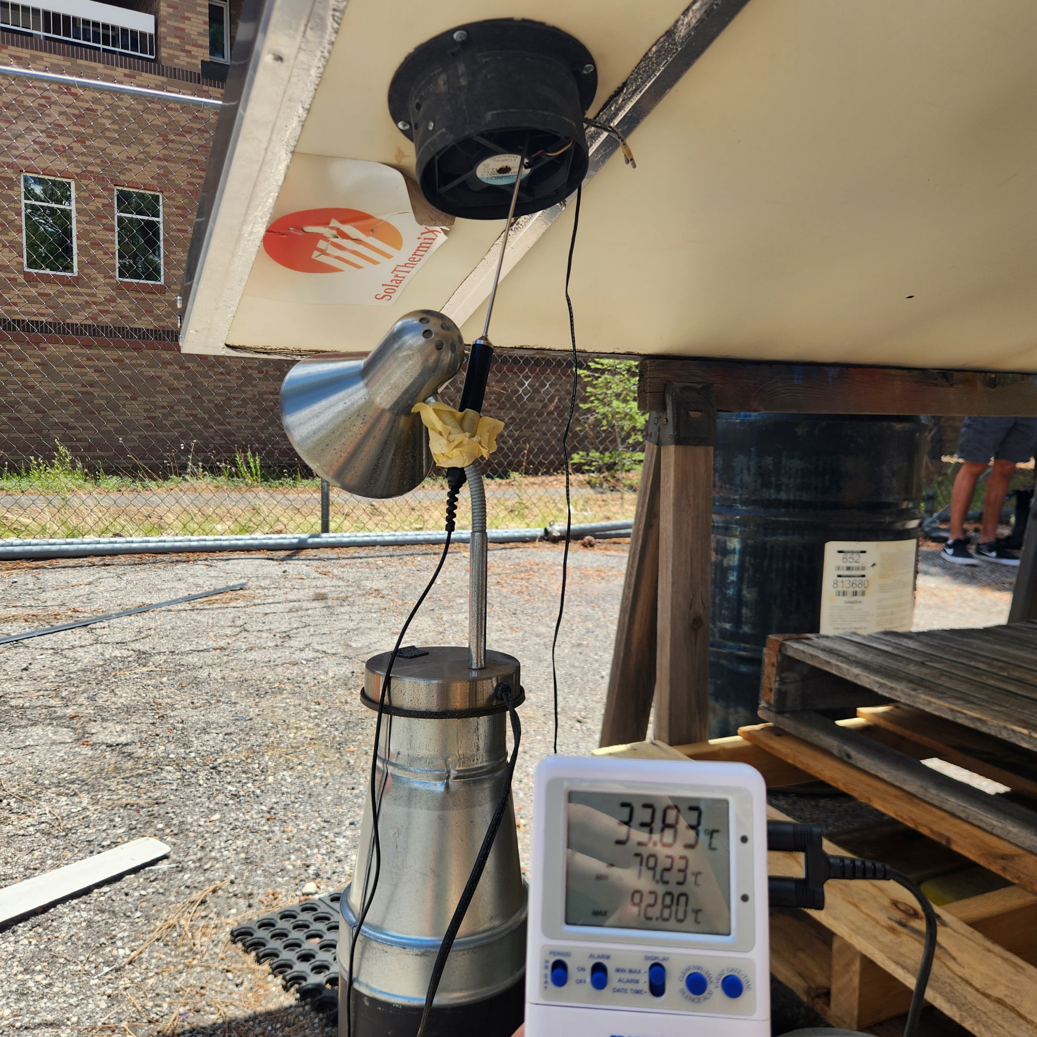
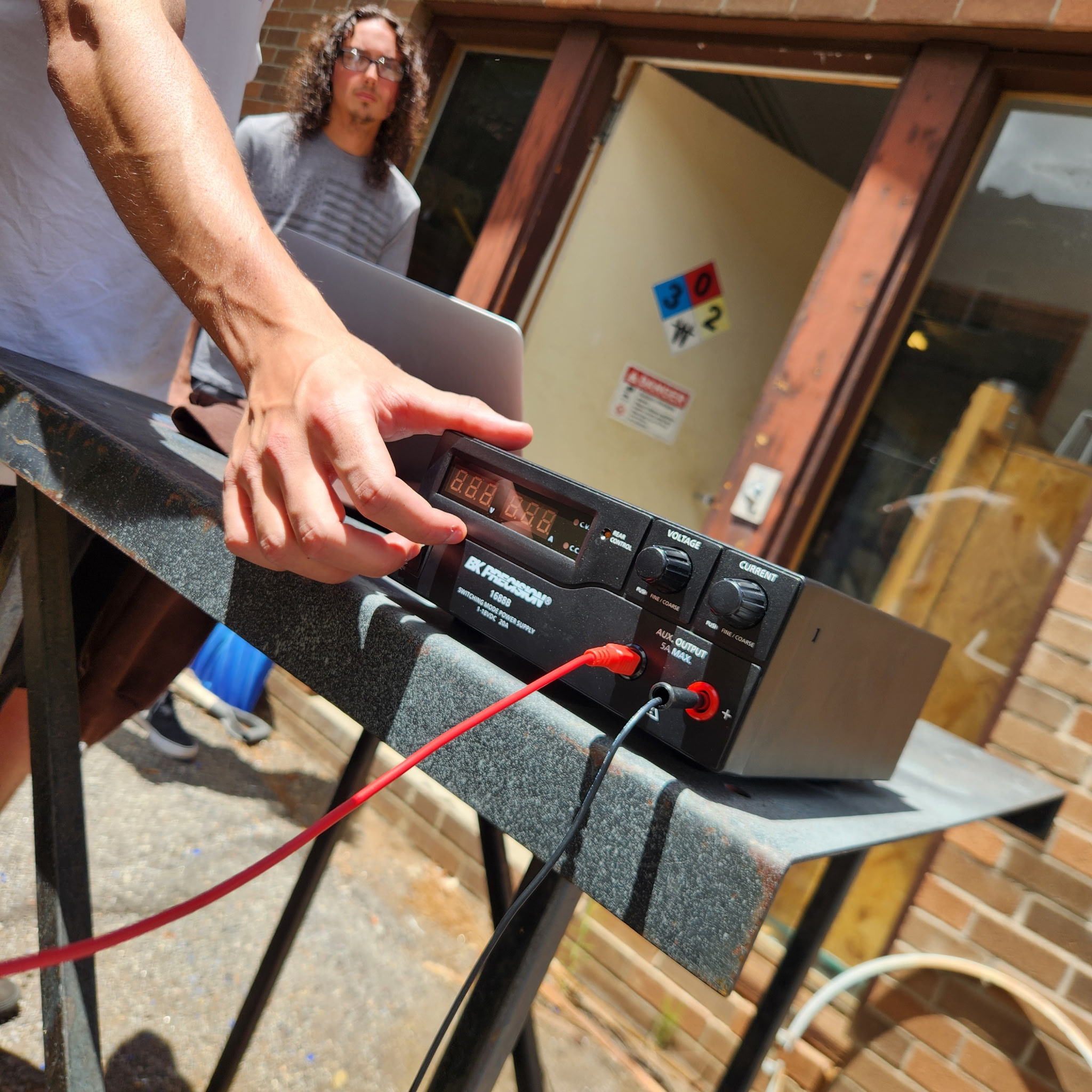
Photo Gallery
Scroll through build and testing photos from the RE Lab Solar Heater Project.