|
Northern Arizona University |


|
Modeling/Analysis 2 |
|
Structural Analysis using Finite Element Analysis One of the requirements for this project was to perform a Finite Element Analysis (FEA) on the thrust reverser. To begin this analysis, the team decided to use the worst case scenario that the reverser could potentially experience. Therefore, a maximum exhaust pressure was applied on the entire reverser plate. This is the worst case scenario because in the actual case, the exhaust will impact the reverser plates similar to the shape of the exit area of the nozzle. This pressure area will be significantly less compared to the FEA model which has the pressure applied to the entire area of the reverser plate. Essentially, the smaller the area the smaller the smaller the force due to pressure will be.
Engine Profile of Exhaust Exit Area
To find the applied pressure (P) acting on the plates, Equation 1 was used.
Where the density (
Fluid Properties through jet engine Fluid Properties through jet engine
|
|
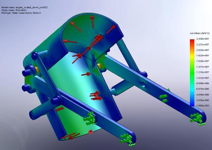
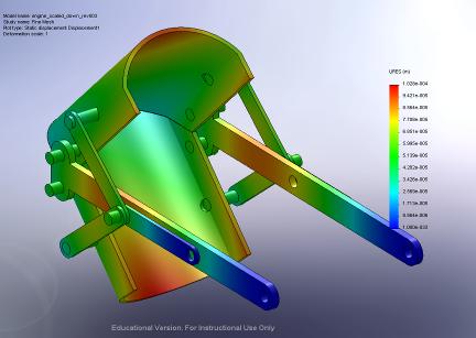
Therefore, the applied pressure that was used in the FEA model was 18,900N/m2. The FEA model was run using COSMOSWorks. From this analysis, the maximum von Mises stresses are 24.3MPa and the maximum displacement is 1.026*10-4m or 1.026*10-7mm. The maximum von Mises stresses occurred at the joints of the linkage system and the reverser plate. Since this could potentially be a point of failure, proper bolts had to be selected. Therefore, stainless steel bolts were selected for their high strength and high temperature capabilities. The major concern was to see how the displacement of metal reacted to the pressure distribution caused by the engine exhaust. From these results, the displacement occurs at the end of the reverser plates and is so small that it is negligible.
Pressure Distribution of Thrust Reverser using Finite Element Analysis
Displacement Profile using Finite Element Analysis
Mathematical Analysis In order to determine the amount of reversed thrust of the final design and to estimate the stopping distance of the aircraft the following known values were used. The velocity of the exhaust from the jet engine is Ve = 300m/s, the area of the exit nozzle of the jet engine is Ae = .0013m2, the density of the exhaust gases is ρe = 4kg/m3, and the total forward thrust produced by the engine is FT=50N. These values were obtained from Model Jet Engines Third Edition by Thomas Kamps, a book that is used by Edwards Air Force Base for the jet engine. The angle of the thrust reverser buckets is θ = 45°. An angle of 45° was chosen because it prevents the engine from ingesting any debris, such as dirt or exhaust, which could cause the engine to stall. If the bucket angles were less than 45°, the engine intake could be exposed to hot exhaust gases, and if the bucket angles were greater than 45°, the engine intake could be exposed to dirt or other harmful elements on the ground. Taking these factors into consideration, an angle of 45° not only prevents the engine from ingesting such debris, but also provides the best amount of reversed thrust.
The mass flow rate (m) of the exhaust was found using equation 2.
m = ρe* Ve * Ae (2)
Using the known values for the exit density (ρe), velocity (Ve), and area (Ae), the mass flow rate of the exhaust was found to be .1638kg/s. In order to determine the amount of reverse thrust, a control volume of the engine and thrust reverser assembly was used. Based on the control volume, equation 3 for the sum of the forces in the x-direction was derived.
∑FRX = m1V1-.5 cosθ(mV)2-.5 cos (mV)3 (3)
Using equation 3, the amount of reversed thrust (FTR) was calculated to be -35N. The percent of thrust being reversed was determined by dividing the amount of reverse thrust by the amount of total forward thrust produced by the engine.
%Thrust reversed = FTR /FT
Therefore the percent of thrust being redirected was found to be 70%. The values for reversed thrust and percent of thrust redirected assume ideal laminar flow.
In order to determine the expected stopping distance of the UAV aircraft using the thrust reverser, equation 4 had to be used. Equation 4 is a second order differential equation.
M dV = -Fdrag – FTR (4) dt
The drag force Fdrag was calculated using equation 5 and varies during landing. For example, the slower the aircraft is going, the lower the friction force value will be.
Fdrag = ½ *ρ*V2*CD*A (5)
Plugging in equations 5 into equation 4, and using a Runge-Kutta MATLAB program, the estimated stopping distance of the UAV aircraft was determined. The solutions to the MATLAB program assume that the aircraft is only using the thrust reverser with no other aides in braking, such as disk brakes or wing flaps.
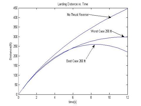
Using MATLAB, a plot for landing distance vs. time was created. In a best case scenario the landing distance of the aircraft is 260ft at approximately 9 seconds. In a worst case scenario the landing distance of the aircraft is 290ft at approximately 12 seconds. These values were determined by taking the maximum point of the curves. The curves decrease after the maximum value because eventually the aircraft will stop, and then the thrust reversers will cause the aircraft to begin reversing. Using these results, it is recommended that the thrust reverser only be used for 9 seconds in a best case scenario and for 12 seconds in a worst case scenario. Not using the thrust reverser, the aircraft will not stop, which makes sense if no brakes are being applied.
MATLAB Plot of Aircraft Landing Distance vs. Time
Kinematic Analysis using MathcadA linear actuator will be used to open and close the thrust reverser. After researching several different options of linear actuators, the Firgelli L12 Linear Actuator was selected because of its compact size, simple to control using industry standard interfaces, low voltage use, equal push / pull force, and easy mounting capabilities. A Mathcad analysis was performed to determine if the linear actuator will be strong enough to open and close the reverser in a timely fashion. It was determined that one linear actuator can produce 12N of force. A reaction force of -14N exist on the thrust reverser due to the friction between reverser components and the high velocity engine exhaust. Therefore two linear actuators will be used to ensure that there will be plenty of force to open and close the thrust reverser. It has also been determined that using the linear actuator the thrust reverser should be able to open and close in approximately 2 seconds.
|