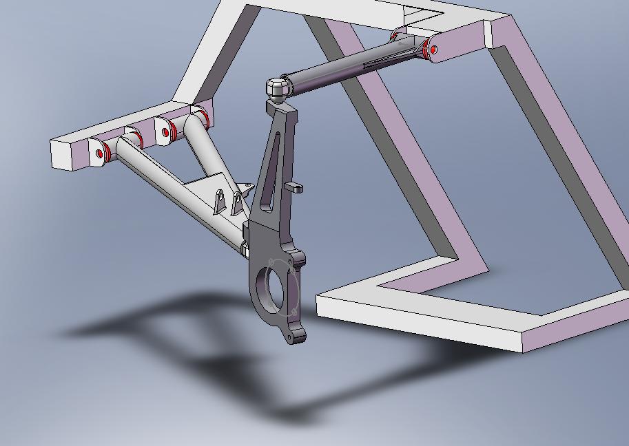
Solidworks rendering of final design:
Finite Element Analysis:
After the team came up with a design that satisfied the requirements and specifications given by the client the validity of the design needed to be checked. Because the vehicle will carry human cargo the strength of the suspension needed to be checked with a worst case scenario of loading the suspension could encounter. To check the strength of the design finite element analysis (FEA) software was used in conjunction with our input force.
With the maximum load the upper arm will ever see the FEA showed a maximum stress of 13,140 psi and a maximum displacement of 0.019 inches. The material yield strength of 50, 990 psi the factor of safety for the upper arm is 3.8. The industry standard for automobile factor of safety is 3. The team opted for a factor safety of this magnitude to insure strength for fatigue loading.
The spindle was also analyzed using FEA. With the maximum load the spindle sees the maximum stress into the part is 15,750 psi. The yield strength of 50,990 psi the factor of safety for the spindle is 3.24. This load gave a maximum displacement of 0.0025 inches of deflection. The team was pleased with the small amount of deflection because of the spindles interaction with bearing components.
Like the other suspension parts the lower arm was also analyzed using FEA. With the complex loading the lower arm sees a stronger material was necessary. The maximum stress inputted into the lower arm from the lateral force is 40,040 psi. This gives the lower arm a factor of safety of 2.24 with the material yield being 89,980 psi. This value is less than the industry standard for factor of safety but it is not overly concerning because the vehicle would most likely roll before seeing this much lateral force.
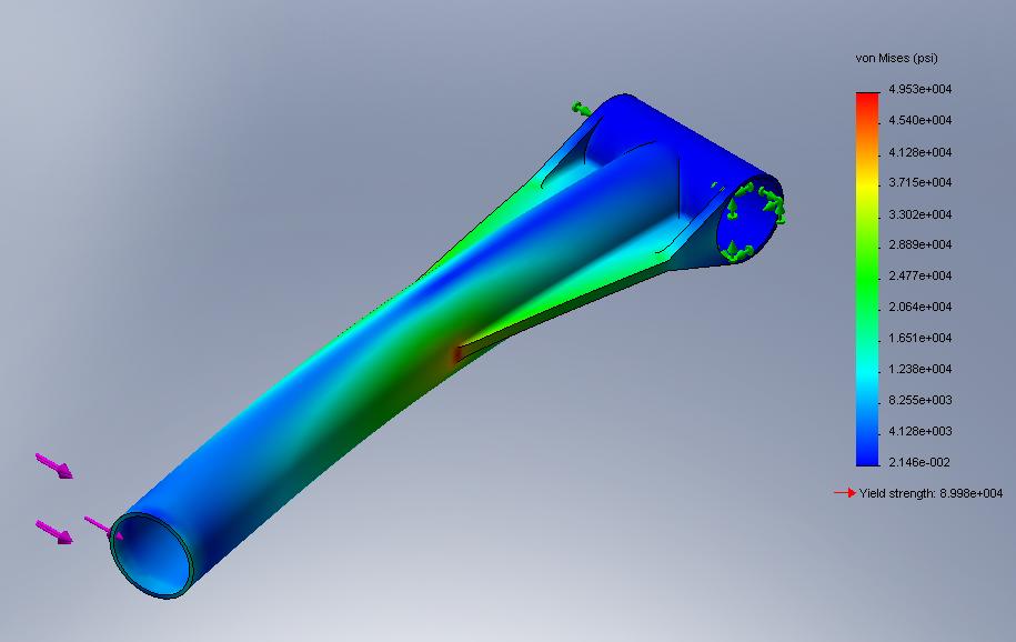
Upper Arm Stress Distribution
Upper Arm Displacement
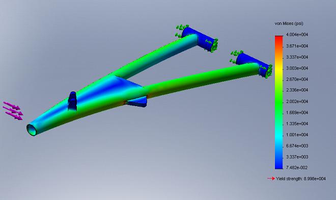
Lower Arm Stress Distribution
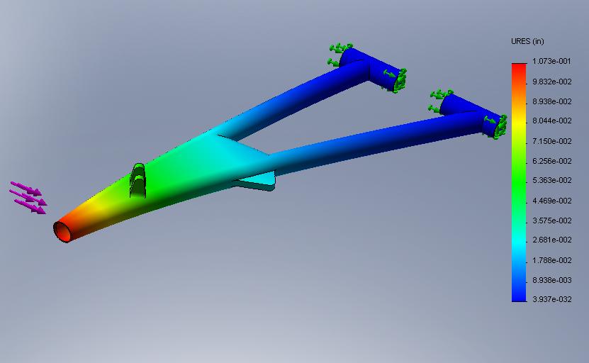
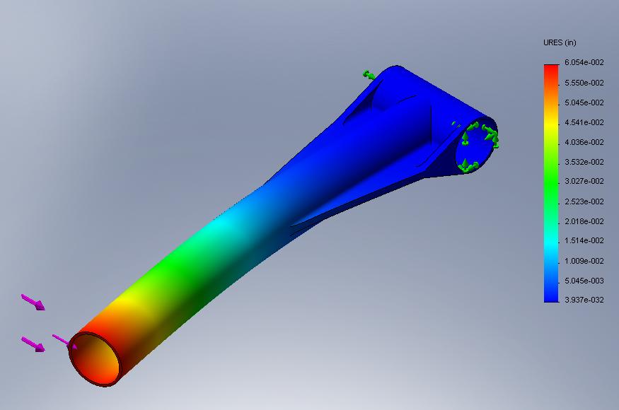
Lower Arm Displacement
We created a video for your viewing pleasure that demonstrates the cycle of the suspension and the caster and camber change is it goes from full droop to full bump.
Click to download video
Simulation:
A simulation in CosmosMotion was performed for comparison to the theoretical input force calculations. The results from the theoretical calculations show similar values found from the kinematics analysis. The input force used in the simulation was obtained using the theoretical calculations. This impulse force, spring stiffness, and damping coefficient were used as a system input to get a desired displacement output for our comparison. The simulation showed a ride height of 10.2 inches under the vehicle weight. When the vehicle experiences the impulse force the deflection is approximately 4.29 inches. The theoretical calculation yields the deflection to be 5.23 inches. These values give a percent error of -17.9. The error in the simulation is due to a shock mount position. The geometry of the frame in the simulation could not be rendered to get the exact same results as the theoretical calculations.
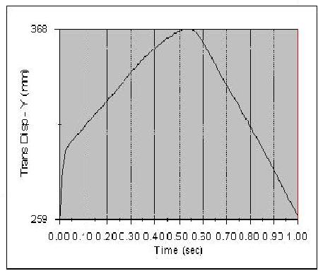
Displacement of Suspension
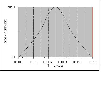
Impulse Force
HOME