awpf Final location

The final location for the AWPF is parcel 101-33-003. The map below shows the parcel selected and location of the force main for the hydraulic design.   

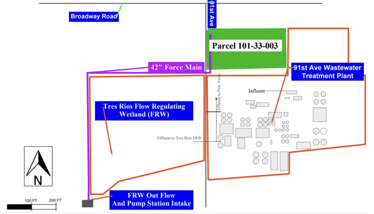
Figure 1: AWPF Site Map

Treatment Train Final Design

Treatment train #3 was selected to be the final design for the AWPF. This was due to treatment train #3 having the best score from the treatment train decision matrix. 

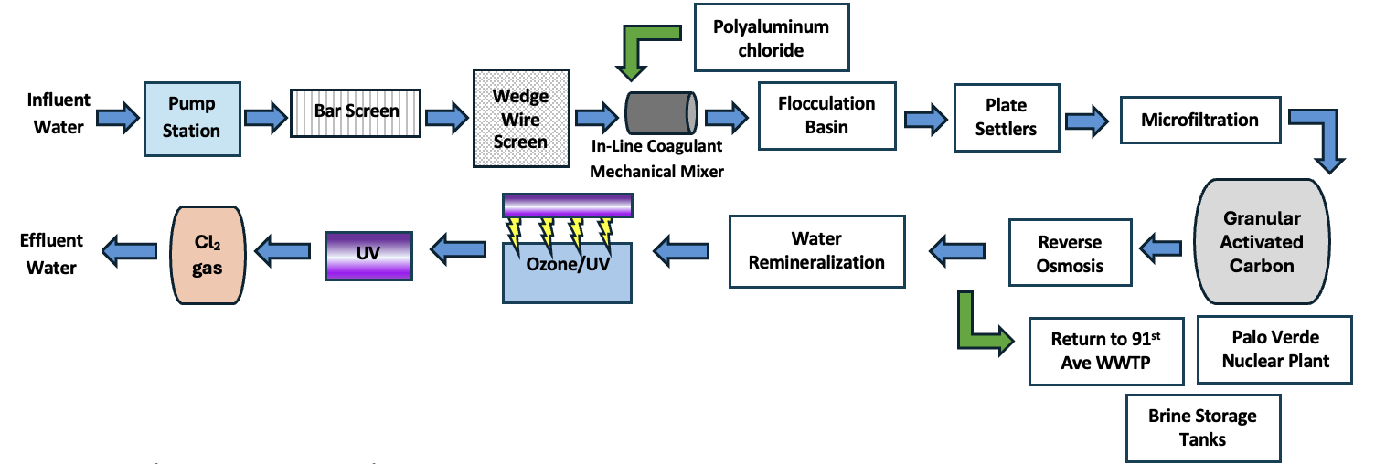
Figure 2: Treatment Train 3 Alternative

Proposed Flow

CJE proposes that 40 MGD of effluent from the 91st Ave WWTP will be delivered to the AWPF along with Palo Verda Nuclear Generation Station (PVNGS), FRW, Salt River, Hayfield Wetlands. The figure below shows CJE's proposed flow from the FRW throughout the treatment train. 

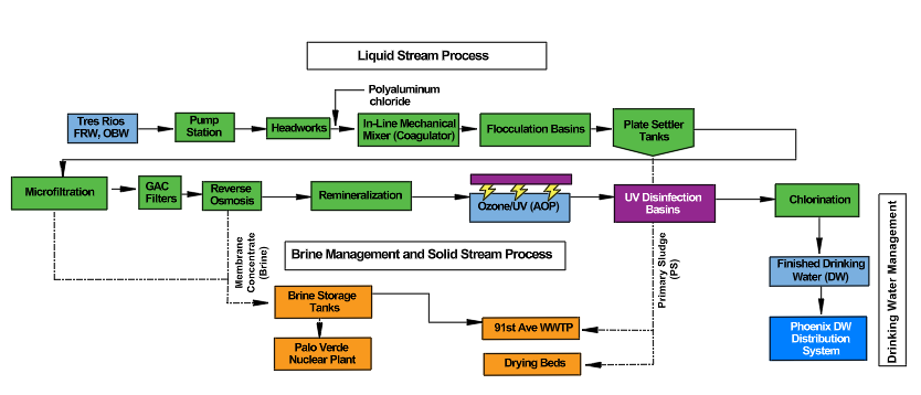
Figure 3: Proposed Flow Diagram

Water Quality Throughout Treatment

The effluent from the treatment train is assumed to be within limits set by the EPA, ADEQ, and MCESD. Below is the simplified water quality table  ​showing the quality of the influent compared to the effluent. The detailed water quality table and assumptions used to calculate can be found in Appendix AX: Water Quality Assumptions and Calculations.

Table 1: Simplified Water Quality Table
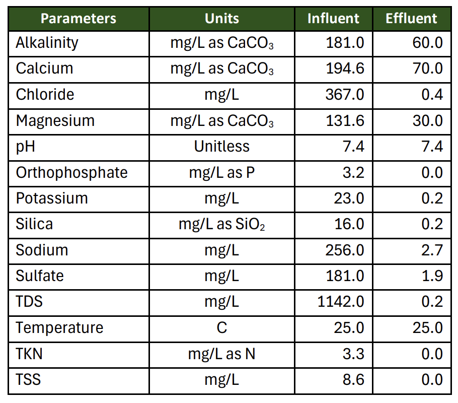
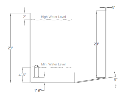
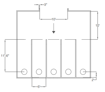
hydraulic Final Design

The final hydraulic conveyance system features 9,900 linear feet of 42-inch AWWA C905 PVC piping driven by five vertical turbine pumps (four duty, one standby) operating at a design point of 40 MGD against 86.18 feet of total dynamic head. 
Examine the plan and profile views below for the intake pump station, detailing the precise structural dimensions, pump bay configurations, and operating elevations required to safely house the vertical turbine pumps. 

Figure 5: ​Detailed Plan View Drawing of Sump Station

Figure 4: ​Detailed Profile View Drawing of Sump Station
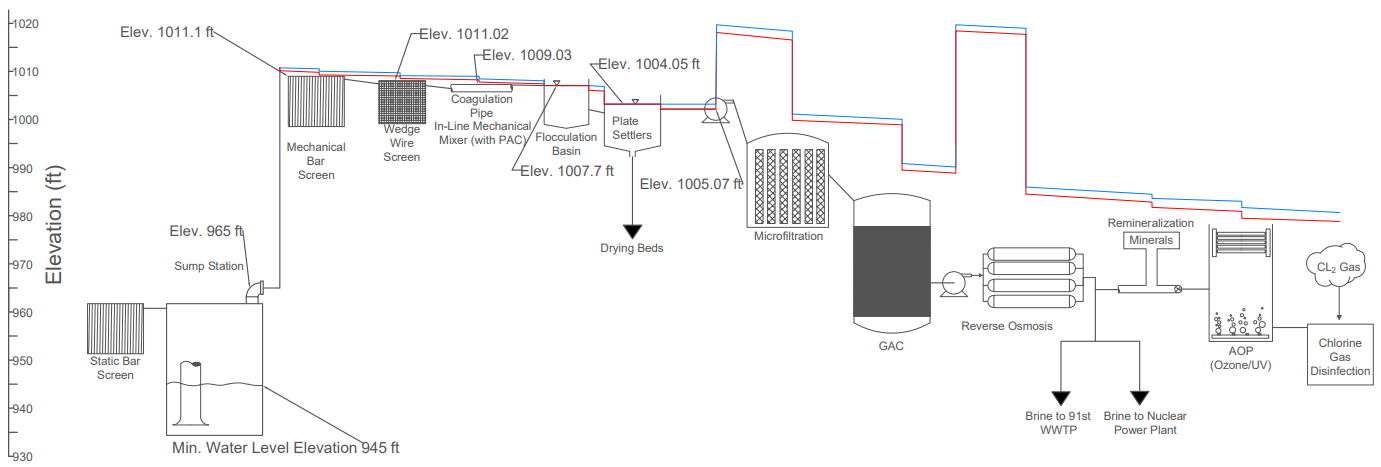
hydraulic Final Design

The hydraulic profile mapping the transition from Pump station to the AWPF Headworks to the final distribution destination.

Figure 6: ​Hydraulic Profile

Site Layout

The optimized 88-acre site layout designed to allow for expansion and minimize connected piping. 

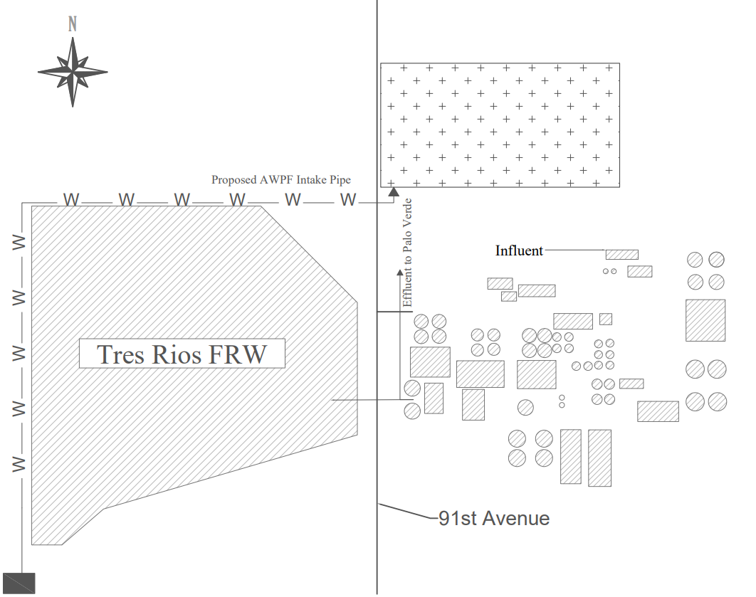
Figure 7: Existing Site Layout
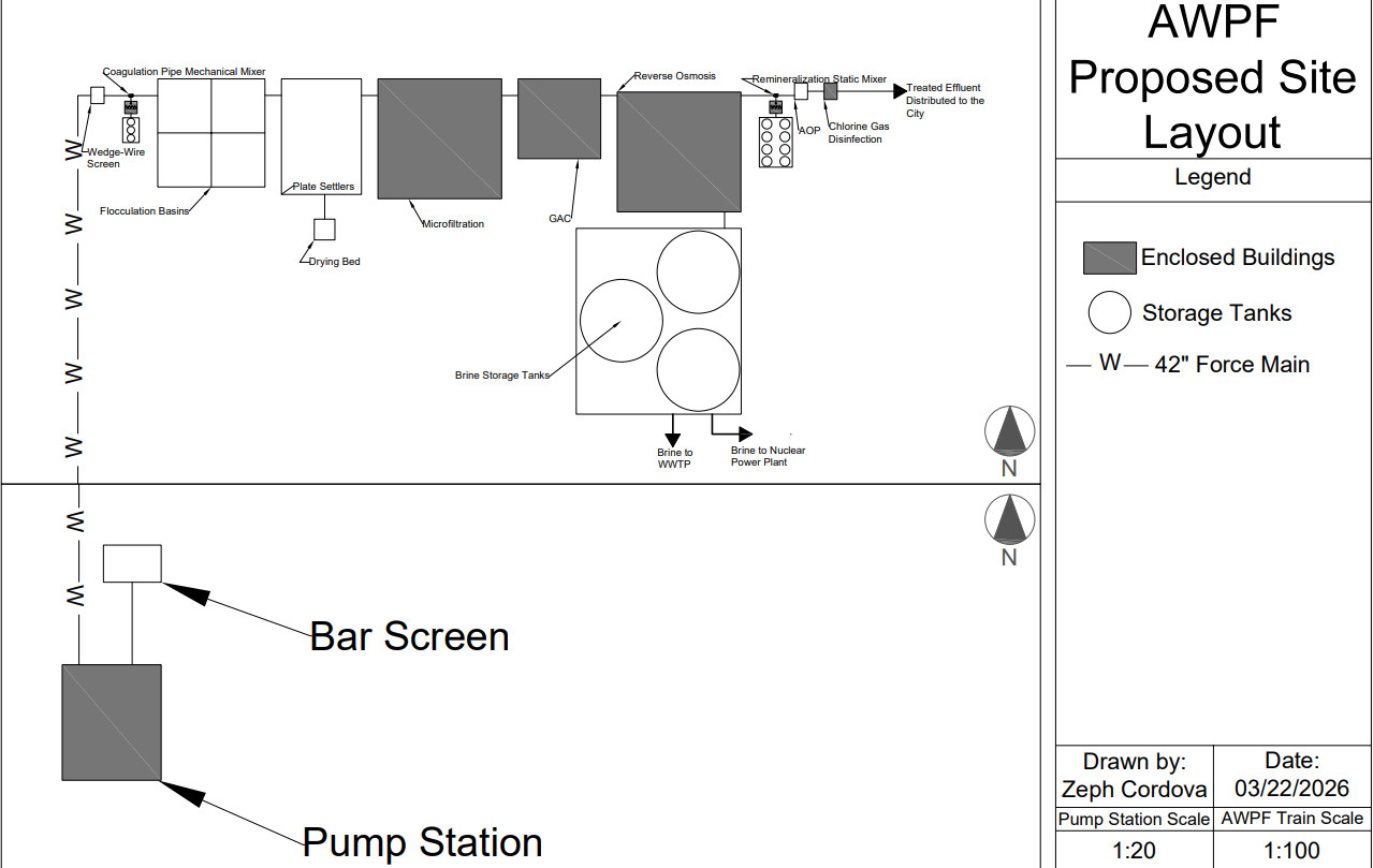
Figure 8: ​Proposed Site Layout